
This Nikon lens had some fungus inside it, so I decided to take it apart and clean it.

If one only wants to remove the glass components and wipe them clean, then very little disassembly is required. That I only knew after spending several hours doing all the wrong things until the lens was all in pieces. (The only components I left alone were the front lens group and the aperture blades.) Never mind, at least I can now provide a fairly complete set of instructions together with a diagram of parts. I suggest you first read through the material in its entirety, and then do as much as you need to, or feel like doing.
We begin by placing the lens on the workbench with its front facing upwards...
 |
Pull out the lens hood and find the screw underneath. Take out that screw and now you can unscrew and remove the front ring / lens hood combo. |
 |
The front lens group comes out as a unit. It screws out anticlockwise. If you are only interested in the lenses (i.e. the glass), then you can now jump to the next section, where we work on the rear of the lens. |
 |
The focusing ring is held with six screws. Take them out. Now you should be able to pull off the focusing ring. It might require a lot of effort though. On my lens the focusing ring fitted so tightly over the inner barrel that I had to use a hammer to remove it. (I put a piece of soft wood between the hammer and the ring to avoid marking it.) Let 's hope, that yours comes off easier. |
 |
Finally, the depth-of-field indicator ring can be taken off after removing the three screws that secure it to the barrel. |
For the next set of tasks, turn the lens over to work from the back of the lens.
 |
The rear lens element can be taken out without much fuss, if you have the right tool. Just unscrew the retaining ring and carefully let the lens drop out when you turn over the barrel. Note, that the flatter side of the lens is facing outwards. (The difference between the two sides is not great, so look carefully, when you reassemble.) If you plan to disassemble the lens further, then it is better to leave the rear lens element in place until later, because it will become easier to get to it when some of the other components have already been removed. |
 |
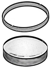
Still working from the back, take out the 5 screws that hold down the shiny steel ring. These screws might be tight - I've seen cases where they were glued in -, so use a good screwdriver. After the screws have been removed, you should be able to separate out the assembly pictured on the left. Note, that there is a trick: set the focus to the closest distance (1.5 meters). Then it will be much easier to pull out this part. Why is this so? That long 'leg' of the aperture stop-down control you see on the picture fits into a narrow gap and as the lens is focused, it slides up and down between two prongs of a small fork. At the infinity setting the 'leg' is far down into the barrel, so due to the tight fit, removal is much more difficult, if possible at all without bending something. |
 |
The aperture scale ring is next. Remove the screw that connects the ring to the matching moving part in the barrel and slip off the ring. (On my lens, the click stops were implemented with a small piece of metal plate with a hump on it rather than the more common steel ball, but other lenses might be different.) |
 |
Our next task will be to separate the focusing barrel and the tube inside it which holds the lenses and the diaphragm. Before we can do this, we first have to remove the black ring at the front. Find the tiny set screw and remove it. Now you can unscrew the black ring. |
 |
During disassembly one, no doubt, paused for a moment or two here and there and, scratching one's head, pondered over how the various parts fitted together to implement an automatic diaphragm and focusing with near and far limits. With the next move, the last pieces of the puzzle will come to light. But before that, let me just point out a few things on this image:
|
 |
When pulling out the innermost tube (with the diaphragm), you might have to take the aluminium tube between two fingers and press your fingers together to force the aluminium tube into a slightly oval shape. This creates some space for the things that stick out of the innermost black tube and would otherwise scratch against the inner surface of the aluminium tube. Naturally, you need to peer inside and see where the problem areas are. (I think you will see what I mean, when you do it.) With this last part removed, the disassembly comes to an end. One could go on and do some more, such as take out the aperture blades, separate the helicoids, etc. but I did not carry this work to those extremes. A final note on what we can find on this component:
|
The assembly procedure is pretty much the opposite of disassembly. The important thing is to understand what goes where (and maybe even why) and to pay attention to such little details as the marks left by set screws, etc. - they give us helpful hints. It will be somewhat challenging to put the rear of the lens back as you need to mate the 'leg' with the fork without seeing them. This is done by feel, but success comes after a few tries.
I think it is clear from the above, that this lens has a very simple construction and no difficult quirks. I can recommend it to first-timers; it only gets more complicated from here.
A note on the 'drawings': Initially, I though I just draw things down on a piece of paper and scan it in, but I wasn't satisfied with the quality and clarity of my drawings. Next I tried the same with the help of a drawing program on the computer. I have a tablet and a pen to go with it, so it appeared to be an easy task. It wasn't. I just couldn't coordinate my hand and eyeballs well enough to overcome the issue of separation between the drawing board here and the resulting image on the monitor over there. So, I ended up taking photographs. But, because I already envisaged documenting this work with drawings (just for a change), I turned the pictures into 'drawings' using Photoshop's Photocopy filter and the Brightness, Contrast, and Threshold controls.
| Click here to leave a comment |